
How to Calculate Deflection Allowance in Drywall Profiles: Ways to Avoid Static Errors
Engineering Fundamentals of Static Safety and Deflection Allowance in Drywall Systems
Although suspended ceiling and partition wall systems are not directly included in the primary structural load of buildings, they require serious engineering calculations due to their own weight and the mechanical loads acting upon them. At HC Drywall Profile, every profile we manufacture is designed by considering the balance between the natural elasticity of metal and structural strength. Incorrect calculation of the deflection allowance during application leads to hairline cracks on drywall surfaces, joint separations, and, even worse, the risk of the system collapsing due to excessive sagging. The first step in avoiding static errors is to correctly analyze the amount of load the profile will be exposed to and the expansion coefficient of the metal.
Application of Deflection Limits and the L/360 Criterion in Metal Profile Design
The amount a drywall profile should deflect is generally determined by the $L/360$ formula in international construction standards. In this formula, $L$ represents the distance between two support points of the profile. For example, the maximum acceptable deflection at the center point of a 300 cm long C-profile is approximately 0.83 cm. HC Drywall Profile technical specifications emphasize that profile thickness and axis spacing must be optimized specifically for each project to ensure these limits are not exceeded. If the calculated deflection is above this limit, the sheet metal thickness of the profile should be increased or the frequency of the hanger elements should be revised.
Necessity of Thermal Expansion and Dilatation Allowance
Metallic structures react to changes in ambient temperature by expanding or contracting in length. Although HC Drywall Profile products are manufactured from high-quality galvanized steel, the laws of physics dictate that an expansion allowance of approximately 1 to 1.5 cm must be left for every 10 meters of continuous line. Especially in large-scale suspended ceilings, pressing the profile ends completely flush against the U-profiles on the walls causes the profile to buckle during expansion, leading to "sagging" of the ceiling. To avoid this static error, gaps must be provided at the end points of the profiles to allow for movement.
The Critical Role of Hanger Elements in Static Load Distribution
In suspended ceiling systems, a large part of the load is carried by hanger rods and brackets (brackets/clips) that connect these profiles to the ceiling rather than the profiles themselves. As stated in the HC Drywall Profile installation manuals, the load-bearing capacity of each hanger element must be calculated according to the weight of the profile used and the number of drywall boards to be placed on it. To prevent a static error, the distance between hanger points is required to be kept between 90-120 cm according to standards. When this interval is exceeded, the moment on the profile increases, forcing the elastic limit of the metal and causing irreversible bending.
Profile Rigidity and Wind Load Analysis in Partition Walls
In partition walls facing the exterior or in spaces with high ceilings, profiles must withstand not only vertical weight but also pressure and wind loads. HC Drywall Profile’s wall C-profiles have a special geometry to resist these lateral pressures. In static calculations, as the wall height increases, the width of the profile (such as 75 mm or 100 mm profiles) and the sheet metal thickness must be increased. Failure to control lateral deflection paves the way for chronic cracks in door openings and wall junction points.
Extra Load Calculation in Double-Layer Drywall Applications
Double-layer drywall applications, preferred for acoustic performance or fire resistance, double the static load on the profile skeleton. According to HC Drywall Profile standards, it is recommended to reduce profile axis spacing from 60 cm to 40 cm, or even 30 cm in some cases, for such intensive applications. When calculating the deflection allowance, not only the weight of the metal but also the weight of the drywall (approximately 25-30 kg/m²) must be included in the equation. Standard installations made without considering this weight cause the system to sag downwards over time.
Effect of Profile Thickness on Static Strength and Screw Holding Power
Low-quality and thin sheet metal profiles found in the market cause the shape of the metal to deform as soon as the screw is driven, creating static weakness. The 0.50 mm and 0.60 mm thick profiles we produce as HC Drywall Profile ensure that the screw is fully locked into the metal. When calculating the deflection allowance, local deformations at screw points should also be considered as a margin of error. If the profile is too thin, screw holes may widen under load, disrupting the balance of the entire system and leading to micro-level movements and, consequently, joint cracks.
Strategies to Prevent Stress Accumulation at Corners and Junction Points
The L-corners where suspended ceilings meet walls are areas where stress accumulates most intensely. Most static errors result from connecting profiles too rigidly at these points. According to HC Drywall Profile expertise, the ceiling skeleton should be in a "floating" structure, independent of the building. Fixing the wall profile (U-profile) to the wall while allowing the ceiling profile (C-profile) to move freely within this channel ensures the damping of energy generated during the building's settlement movements. If this elasticity allowance is not provided, breakage starts from the corners, which are the weakest link of the ceiling.
Hanging Principles for Installation Loads and Mechanical Equipment
Ventilation ducts, heavy lighting fixtures, or fire installations are often attempted to be loaded onto the drywall profile skeleton. However, this is a major risk from a static perspective. In HC Drywall Profile systems, an independent hanging system must be established for any additional load exceeding the load-bearing capacity of the profile. If the installation is to be connected to the profile, the number of profiles in that area should be increased, and the skeleton should be reinforced with additional support profiles. When calculating the deflection allowance, it is recommended to include these unforeseen loads in the system with a 20% safety margin.
Indirect Effect of Corrosion on Static Strength in Humid Environments
In projects in bathrooms, kitchens, or by the sea, corrosion is the biggest enemy that disrupts the structural integrity of the metal. A rusted profile loses its elasticity and the metal becomes brittle. The high-micron galvanized coating used in HC Drywall Profile products prevents the oxidation of the metal, ensuring that static calculations remain valid for decades. When calculating deflection allowance in humid environments, the safety factor should be kept higher, assuming the metal may weaken over time, and accessories with high corrosion resistance should be preferred.
Damages of Incorrect Profile Cutting to System Stability
One of the most common static errors made at construction sites is cutting profiles with the wrong equipment and deforming the ends. A crushed profile end does not fit perfectly into the U-profile and performs an unbalanced load transfer. HC Drywall Profile advises users to use shears or saws that will not damage the mouth structure of the metal during cutting operations. When the geometric form of the profile is distorted, the strength values do not match the data on paper, causing surface defects due to local deflection differences.
Use of Reinforced Profiles in Long Corridors and Wide Spans
In long and narrow areas like corridors, a pressure difference in the upward-downward direction can occur due to the wind tunnel effect. In such cases, the deflection allowance of standard profiles may be insufficient. The HC Drywall Profile technical department suggests using box profile reinforcements or main carriers with thicker sections in these types of special areas. To reduce the static error margin to zero, it is a structural necessity to check the deflection calculation every 2 meters in long spans and to arrange the junction points of the main carrier profiles in a staggered manner.
Effect of Screw Frequency and Layout on Profile Deflection
The frequency with which drywall is screwed to the profile determines the ability of the system to move as a whole. Driving screws too frequently locks the profile excessively, while driving them too sparsely causes the board to deflect independently on the profile and the screw heads to snap off. In HC Drywall Profile installation standards, a screw spacing of 25-30 cm, and reducing it to 15 cm at corner finishes, provides the ideal static balance. This layout ensures homogeneous distribution of the load on the profile, preventing local deflection accumulations.
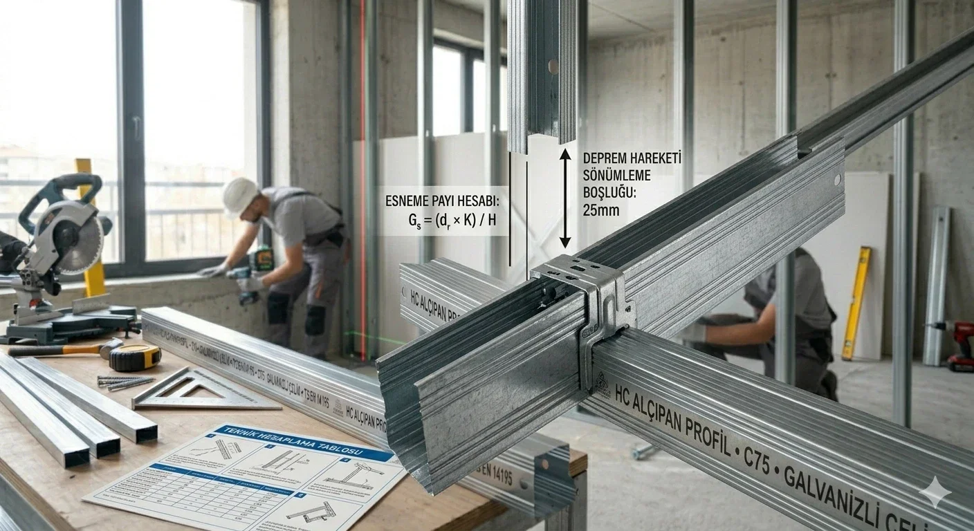
Building Movements and Seismic-Isolator Profile Applications
Especially in regions located in earthquake zones, micro-level oscillations of buildings are a major source of stress for drywall systems. Seismic gaps and flexible connection elements should be used to avoid static errors. HC Drywall Profile allows the ceiling to move with the building but without breaking, thanks to its clip and bracket systems that have expansion capacity suitable for seismic designs. While a rigid and non-flexible system collapses at the slightest tremor during an earthquake, systems with correctly calculated deflection allowance preserve structural safety.
Correct Determination of Ground and Ceiling Levels Before Installation
Some static errors actually start at the very beginning of the installation with leveling mistakes. In a profile skeleton aligned to a crooked level, the load distribution becomes asymmetric. While the load on the profile on one side remains within calculated limits, the profile on the other side may be overloaded. The use of a laser level in HC Drywall Profile applications guarantees equal distribution of the load across the entire skeleton. Equal load distribution ensures that the deflection allowance remains the same at every point, helping the ceiling or wall maintain its aesthetic form for a lifetime.
Construction Site Waste and Economic Profile Length Optimization
Selecting the correct profile lengths during the project phase both reduces costs and increases static strength by reducing junction points. HC Drywall Profile prevents the use of unnecessary junction pieces by producing custom lengths for your project. Every junction point carries a potential weak point from a static perspective and changes the deflection characteristics. Skeletons established with continuous profiles are the systems that show performance closest to the calculated deflection values and have the lowest static error margin.
Safe and Long-Lasting Applications with HC Drywall Profile
In conclusion, deflection allowance in drywall systems is not an error but an engineering parameter necessary for the healthy operation of the system. The important thing is that this deflection remains within controllable limits. As HC Drywall Profile, we offer technical features to ensure this control in every part that comes off our production line. When the correct profile choice, the correct axis spacing, and professional workmanship come together, it is inevitable to create aesthetic and safe living spaces far from static errors. By choosing HC assurance in your projects, you can build both today and the future on solid foundations.